Review Observations
Record a Manual Observation
A shower situated in the mechanic’s shower room does not have RCD protection, therefore, when we go next onto manual preset observations this is a reminder on how to record them.
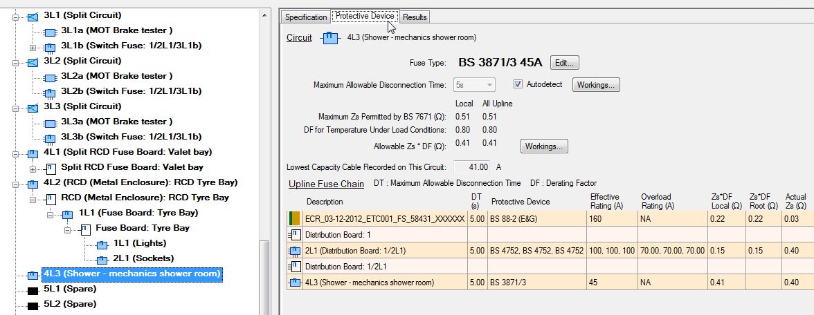
Click the |new observation icon| button.
The New Observation dialog is displayed.
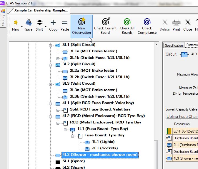
In the “Preset” textbox, enter a keyword e.g. “bathroom”, “shower”, or “701”.
A list of preset diagnoses relevant to bathrooms and showers pops up.
- Bathrooms and showers are classed as Special Locations under section 701 of the Regulations. This feature provides a useful memory prompt for Special Locations that the inspector may not be familiar with.
- The list shows diagnoses pertaining to the keyword, and/or diagnoses containing the keyword.
- If you enter a phrase, only diagnoses containing that exact phrase are shown.

To choose a preset observation from the popup list, click on it.
The diagnosis is copied to the Preset textbox.
- Note:
- Don’t forget to apply this observation to all circuits having items of equipment within the shower room including lighting points. If you are happy with the default severity and verified that the correct circuit has been applied enter “OK”.
Reduced Low Voltage Systems
We have a fuse board that is fed from a 110 V transformer. The circuits are feeding reduced low-voltage sockets in the workshop. Reduced low-voltage must not be confused with extra-low voltage systems (<=50 V) as the touch voltage (55 V) is greater than the minimum allowed (50 V).
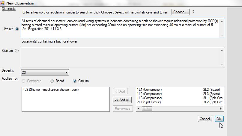
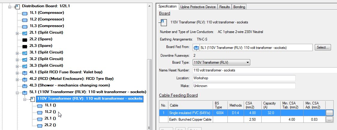
In the left tree, right click on the supply circuit (5L1) then select “New” -> “Board”.
The “New Board” dialog is displayed.
Under “Type” select “110v Transformer (RLV)” then enter the board details as normal.
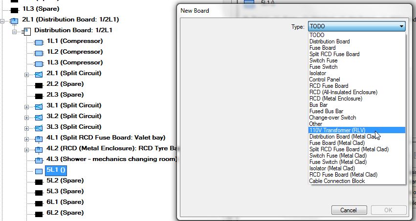
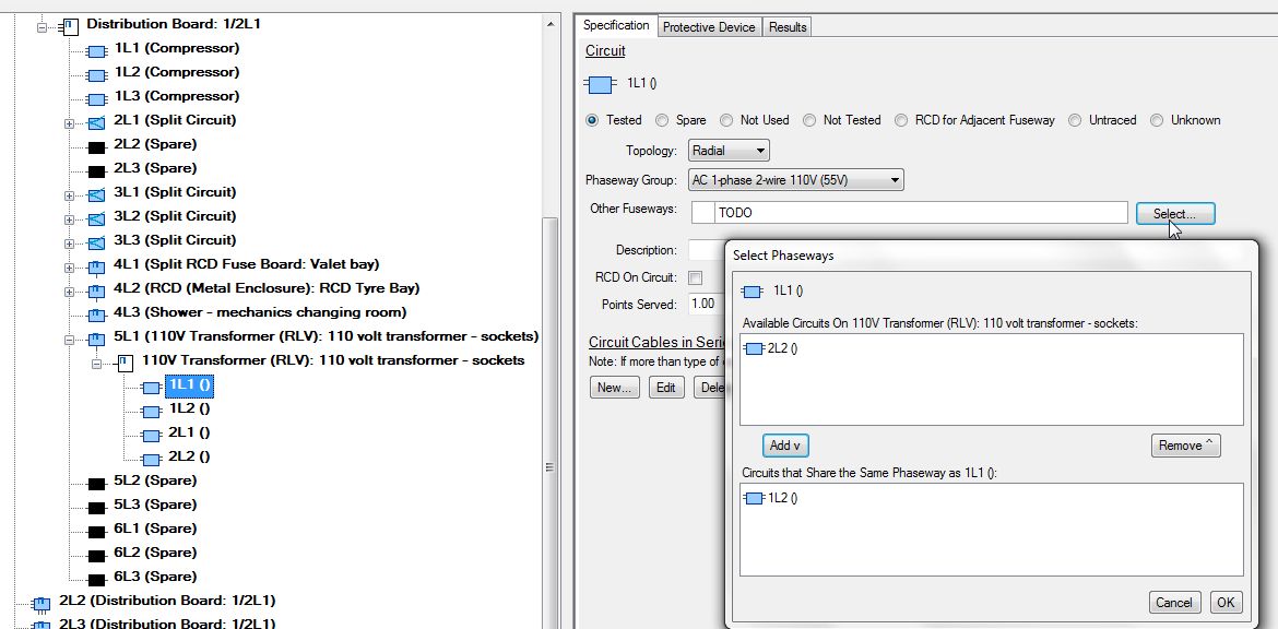
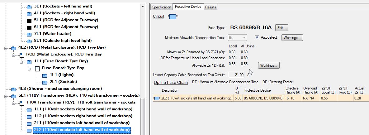
Here you can see that the fuseways formed are similar to a 2-phase board, but having a single phase supply. The reason that there are 2 x fuseways per circuit is that the regulations require that both line conductors of a 110 V circuit have earth fault protection by means of an over-current protective device, or by an RCD.
- Select the “other” phaseway belonging to each 110 V circuit.
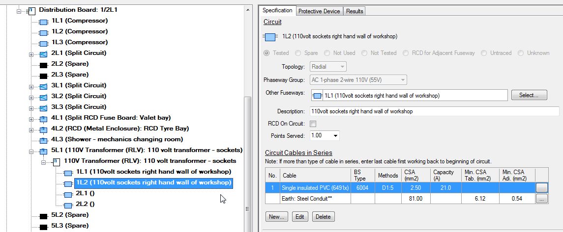
- Once you have entered the data for the first phaseway, use copy and paste it to the second fuseway.
If there is no protective device on the second fuseway, enter “Solid Link”.
This has been entered so the circuit will offer an observation in relation to the earth loop for both line conductors being protected against an earth fault. As an example, here I have entered a “Solid Link” for the second phaseway of the first circuit, therefore there is no “Allowable Zs” defined and auto-observation(s) will be offered.
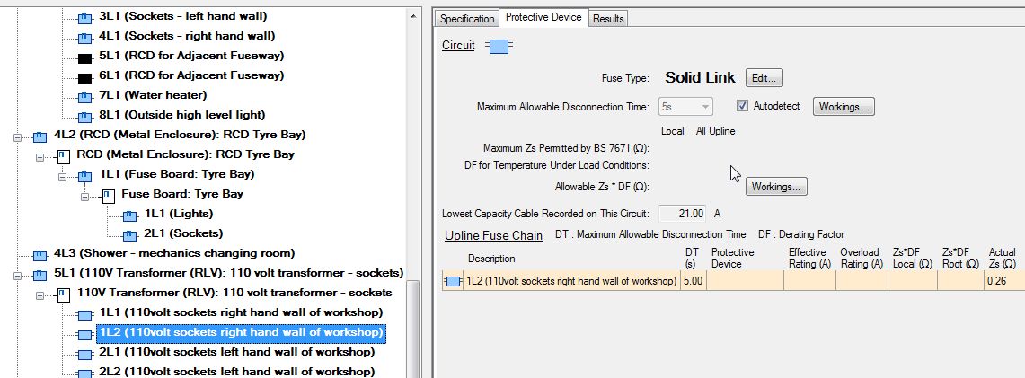
Here, both phaseways have protective devices; therefore the “Allowable Zs” has been calculated and will be also calculated for overload protection.
Run Checks
Click the |check all boards icon| button to check that all data has been filled in.
If there are any fields on the certificate that have not been filled in they will be listed in a window in the bottom right of the screen. Clicking on an item in this list will display the missing field.

- Click the |check compliance icon| button.

Once diagnostics have run, any circuits or circuits or boards with “Unassigned Observations” will be marked in the left tree with a blue exclamation icon, as per the key in the top right hand corner of the Certificate Window.
A list of Unassigned Observations and their symptoms open in the bottom of the window. Clicking on an item will take you to the relevant section, board or circuit.
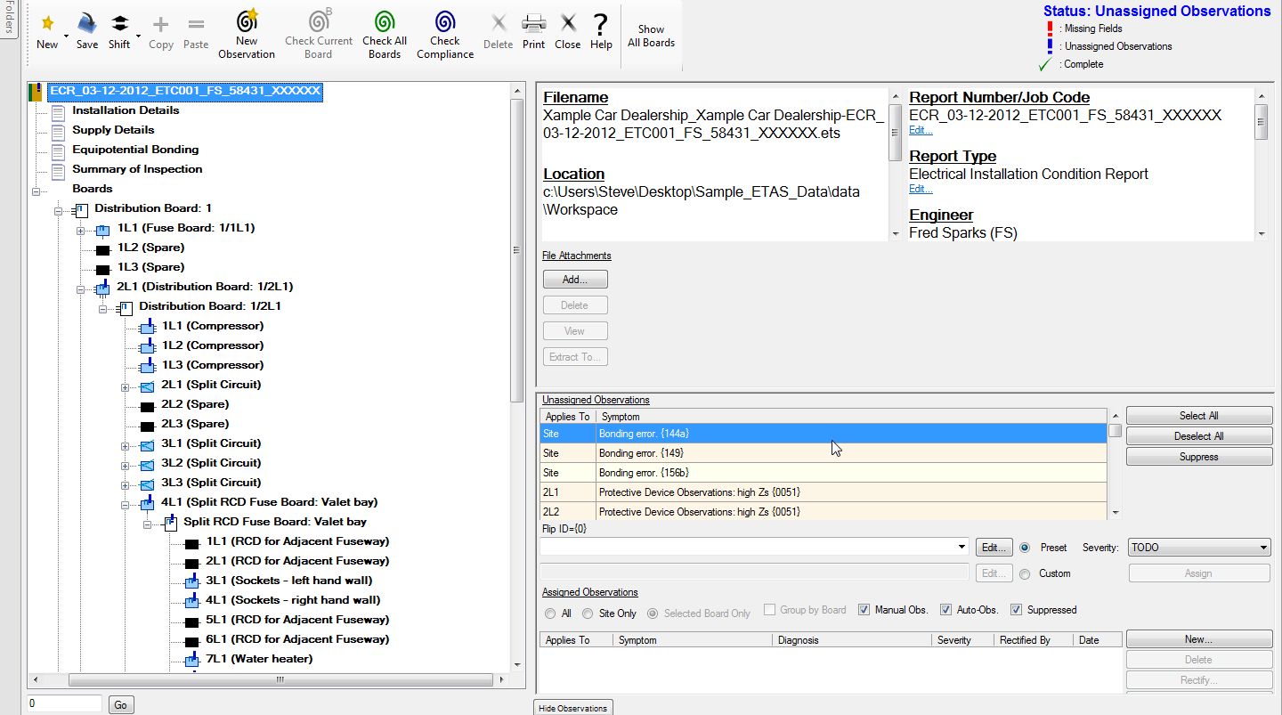
Click the first symptom, “Bonding error 144A”.
In the box below, a diagnosis will appear.
As this is the only diagnosis listed, click on it to enter the diagnosis.

You can edit any “Preset” diagnosis by clicking on the “Edit” button. This will bring up a screen in which you can carry out the editing. In this instance we will accept the diagnosis as it is. You can also, if you wish, not accept the default “Severity”. If you wish to change it, use the drop down feature and choose another severity. If you are happy with the diagnosis, using the “Assign” button, will move it into the bottom “Assigned Observations” pane. This will be added to the “manual Observations” entered earlier.
Most symptoms will offer more than one diagnosis, this enables the inspector to pick the closest he feels, is relevant to the required observation, not forgetting of course that the chosen observation maybe changed or expanded upon.
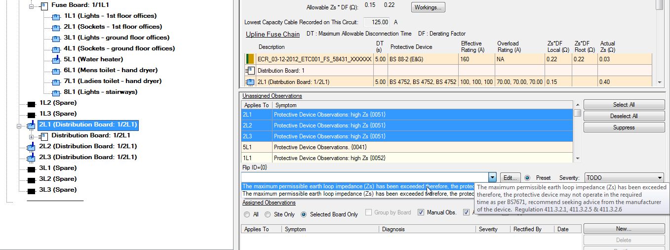
If you have multiple symptoms (having the same number in brackets on the end) within the same board, in this case {0051}, you can highlight all the symptoms by using the shift or control key and your mouse and apply the chosen observation to all three in one action, this is especially useful for a common observation in the case of multi-phase circuits, where choosing the same diagnosis from a list of more than one.
Suppress an Automatic Observation
In some cases it may be required to suppress auto observations where, in the inspector’s opinion there is no risk.
For example: A ring-main has been installed in the workshop. The maximum ring continuity reading for a standard ring-main R1 - R1 should be no more than approximately 0.73 Ω (98 m of cable length) for an average load of 26 amps. Although the ring continuity is excess of 0.73 Ω (in this case 0.9 Ω), it has been ascertained that the majority of tools in the workshop are air driven and therefore the ring-main is under used, with the result that there is no real risk of voltage drop due to light loading and therefore you wish to “suppress” the auto observation.
- In the “Unassigned Observations” pane, click an auto observation that you want to suppress, then click the “Suppress” button.
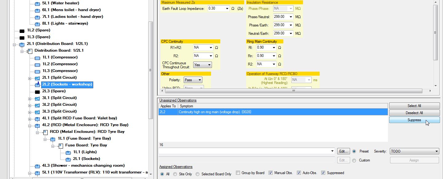
- Enter the reason for suppressing this observation and click OK.
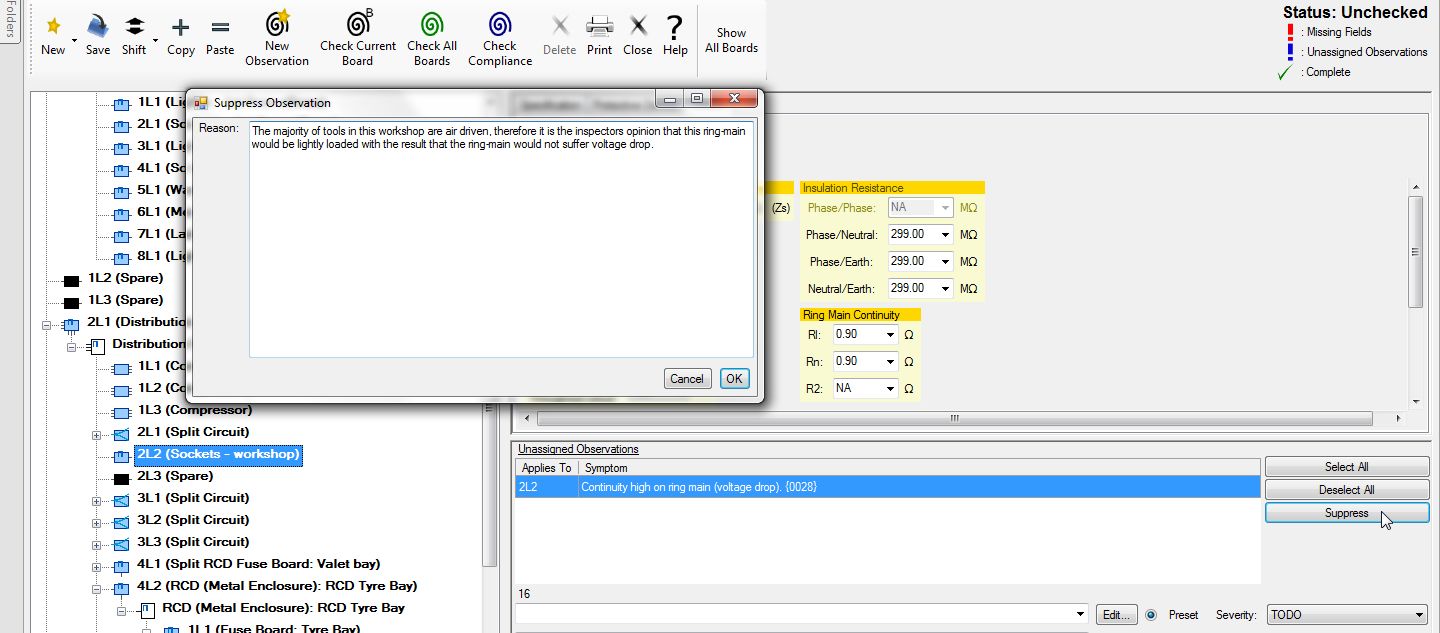
The observation will be moved to the Assigned Observations list and is displayed with a line struck through it to show that it has been suppressed.

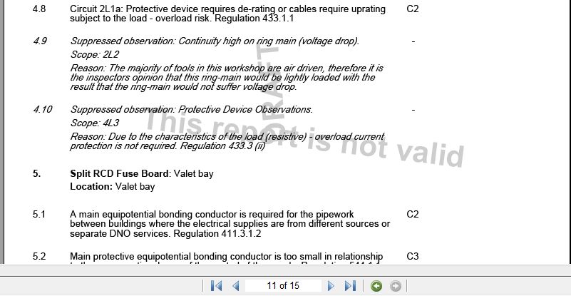
The suppressed observation will be shown on the report in an italicized font with both the symptom and the reason for suppression. This enables the reviewer and Client/End user to see that you have recognised the length of the ring-main which in some circumstances, could suffer voltage drop from the loads placed upon it, but recognising that the ring-main would never, in this instance, suffer voltage drop from the amount of load placed upon it, have not failed the circuit. This saves the inspector and/or testing company from having the report being called into question.
Potential Overload
This circuit supplies an immersion heater having a resistive 3 kW (13 amp) load. The cable has a current carrying capacity of 20 amps protected by a 25 amp protective device. The cable does not have any spurs between the protective device and the load. Therefore overload protection is not required as per regulation 433.3.1, the protective device is protecting against fault current only.
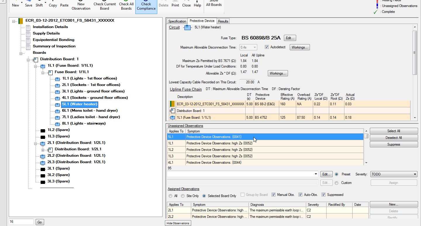
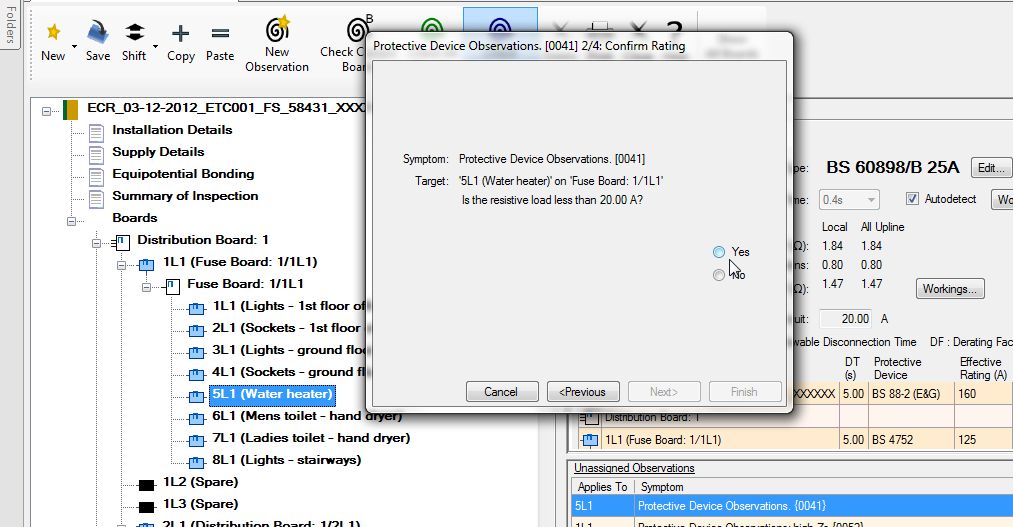
Click on “Protective Device Observations {0041}”.
A wizard will pop open.
In this instance, because of the nature of the load, we click “Yes”.
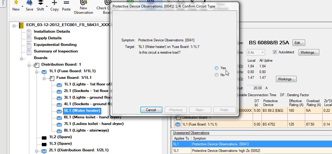
A third screen will appear stating that the observation will be “suppressed”. Again, the suppressed observation will be shown on the report in an italicized font with both the symptom and the reason for suppression. In the list of “Assigned Observations”, it will show in a non-italicized format with a line struck through.
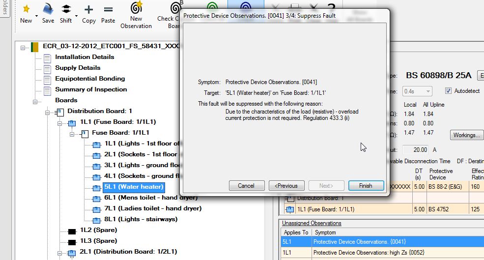
This enables the reviewer and Client/End user to see that you have recognised the potential over sized protective device, but due to the type and size of load have not failed the circuit. This saves the inspector and/or testing company from having the report being called into question.
Click Finish.
The unassigned suppressed observation will be moved into the bottom assigned observation screen with a line through it to show that it has been suppressed.

If this circuit was not a resistive load or could overload the circuit, then click “Previous” to going back to the first pop up screen and click on “No”.
A second screen will replace the first where you can choose an observation. If for any reason the first pop up screen will not appear, come off the highlighted unassigned observation onto another one and then go back to the original unassigned observation in question.
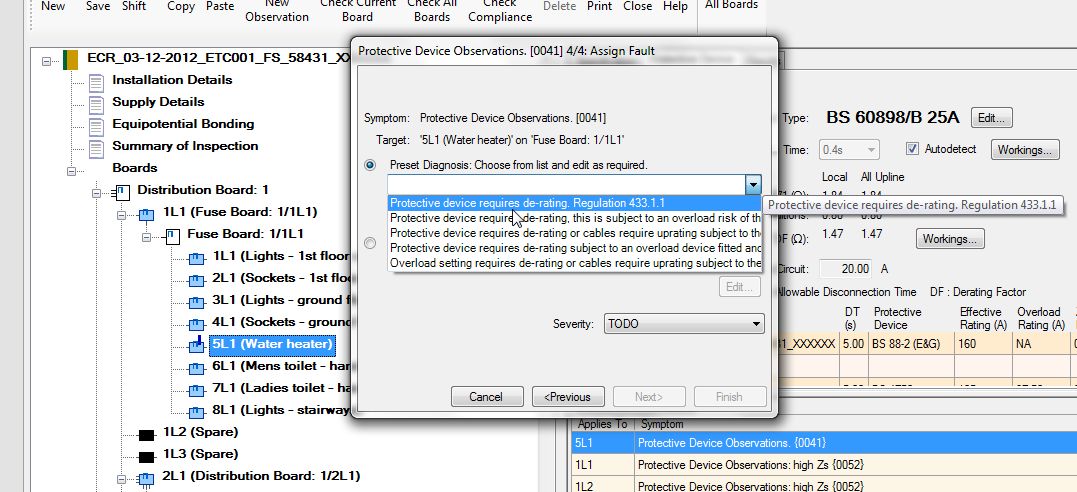
Repeat the steps above for all observations in the “Unassigned Observations” list.
When all observations are assigned, the “Unassigned Observations” will collapse leaving only the “Assigned Observations” list.
When you are happy that all manual observations have been entered, you would normally click on the |check compliance icon| button again. But before we do that, in the left tree select “Summary of Inspection”.
Note that all items are set to “TODO”.
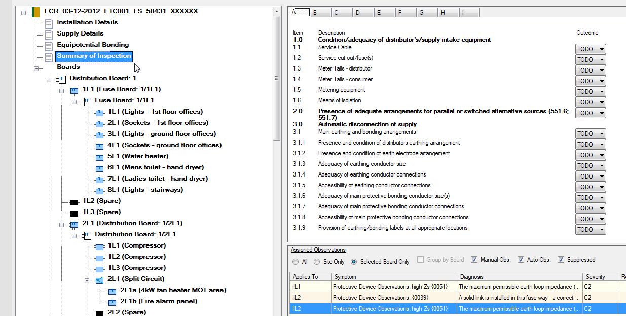
Click the |check compliance icon| button.
A dialog box will be displayed showing items that will be “flipped” automatically based on the all the manual observations that have been recorded or auto-observations that have been assigned.
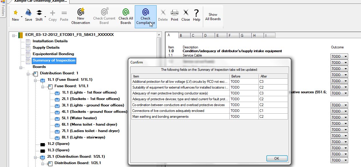
Click OK.
The program will check for missing fields and list them in the bottom of the window. Confirm fields have been “flipped” and which fields remain as “TODO”. You can if you wish, hide the list of missing fields in the bottom pane by clicking the “Hide” button on the lower right.
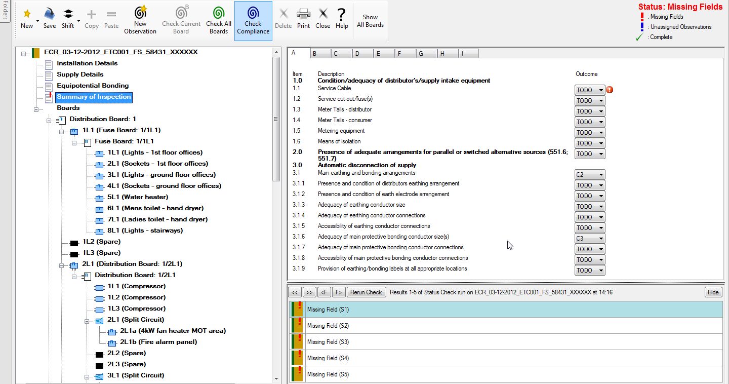
➲ Next: Fill in the Summary of Inspections.
